Final Project: Rocket Design and “Fly”
UB-MAE 423: Introduction to Propulsion
The project aims to design a sounding rocket given a set of design parameters, with the focus of maximizing the efficiency.
Table 1: Design Input Parameters
| Input Parameter | Description of Parameter | Assigned value |
|---|---|---|
| M_L | Payload mass | 1 Kg |
| h_max | Maximum altitude | 10k, 20k, 20k |
| a_star_max | Normalized max. acceleration | 5, 10, 20 |
| SM | Static margin = (X_CP - X_CG)/D | 1, 2, 3 |
| rho_s | Shell (Aluminum) density | 2700 |
| rho_p | Propellant density | 1772 |
| sigma_s | Shell working stress | 60 MPa |
| N | Number of fins | 3 |
Table 2: Design Output Parameters
| Output Parameter | Description of Parameter |
|---|---|
| R | Initial to burnout mass ratio |
| W_eq | Equivalent/effective velocity of gas at nozzle exhaust |
| t_b | Burn time |
| P_o | Exit Pressure |
| D | Diameter of the rocket tube/ Height of rocket nose and fins |
| L | Length of the rocket tube |
| delta/D | Thickness to D ratio |
| X_CG | Center of mass/gravity |
| X_CP | Center of pressure |
| M_P | Propellant mass |
| M_o | Total mass |
| lambda | The ratio of the specific heats |
| epsilon | The ratio of mass, M_s/(M_P + M_s) |
The rocket geometry under consideration for this project is as follows:
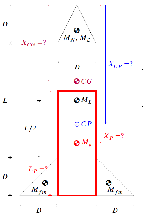
Figure 1: Parameterized Rocket Geometry.
Results:
Part I
Design changes with maximum altitude, h_max variation:
Figure 2 (a & b) below shows that for the increase in maximum height from10,000 ft to 30,000 ft, the required burn time and velocity increases by around 40%. While the burn time and equivalent velocity are so impactful to attain a higher destination, the X_CG and X_CPdoes not change drastically for the higher altitude. The changes in the X_CG and X_CP are in fact less than 1% for variations in h_max.
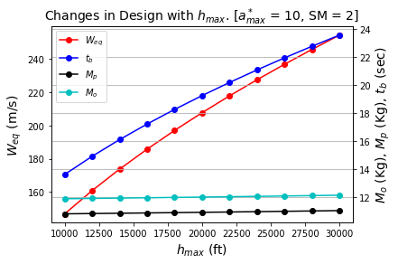
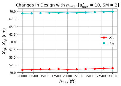
(a) (b) #### Figure 2: Design changes for h_max variation
Design changes with normalized maximum acceleration, a_max^* variation:
The lower value of 5 and the upper value of 20 was under consideration to understand the effect of a_max^* change. For higher acceleration, the burn time and velocity logarithmically decrease in around 50%. Therefore, it shows that to achieve a higher acceleration for a rocket, it is very crucial to select a propellant and rocket structure that can efficiently minimize burn time. Also, the weight of the propellant, as well as the overall structure has a negligible (around 2%) effect on acceleration.
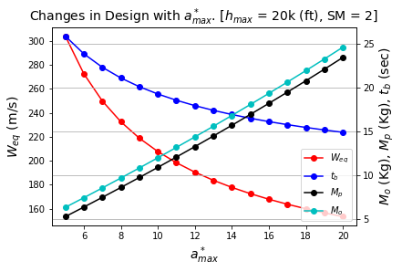
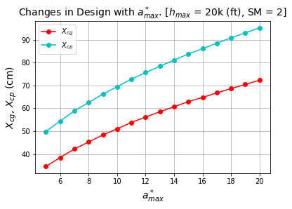
Figure 3: Design changes for a_max^* variation
Part II
The designed rocket was simulated with the baseline condition h_max=20,000 ft,a_max^*=10,SM=2 The simulated results as ovserved from OpenRocket are lsited below:
Ideal Vertical Case:
In an ideal situation we neglect the drag effect, which allows assuming ideal case with maximum efficiencies. So, the expected performance is much higher than the realistic condition. For idealized case, the h_max,V_(r,max) and a_max^*, with respect to the flight time is shown in the Fig.4 below:
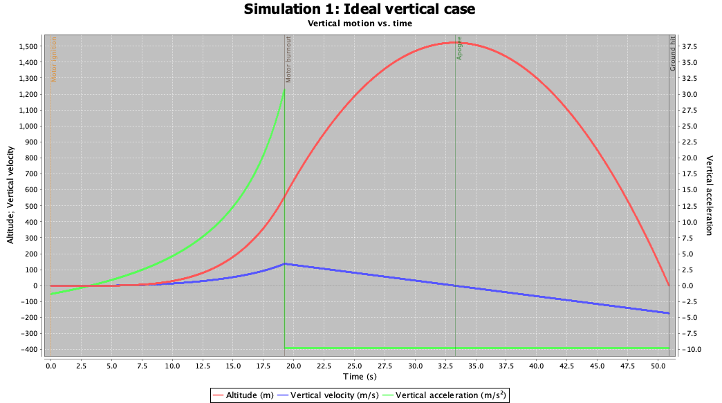
Figure 4: Rocket performance profile for ideal case (Drag force=0)
The simulation agrees to the calculated value of with 6% error in maximum height and 3% in acceleration. The rocket also satisfies the baseline conditions with approximately 7% error. This result makes sense as the performance profile agrees with the theoretical height, velocity, and acceleration values.
Drag Effects:
Figure 5 below shows the realistic performance profile for the rocket under the drag effects. If compared to Fig. 4, the results show a significant decrease in performance as expected. This result because the effect of drag is very impactful in rocket performance as opposed to ideal conditions with no drag. So, with the addition of drag effects, the rocket with same design shows around 74% performance decay from the baseline condition under ideal case consideration.
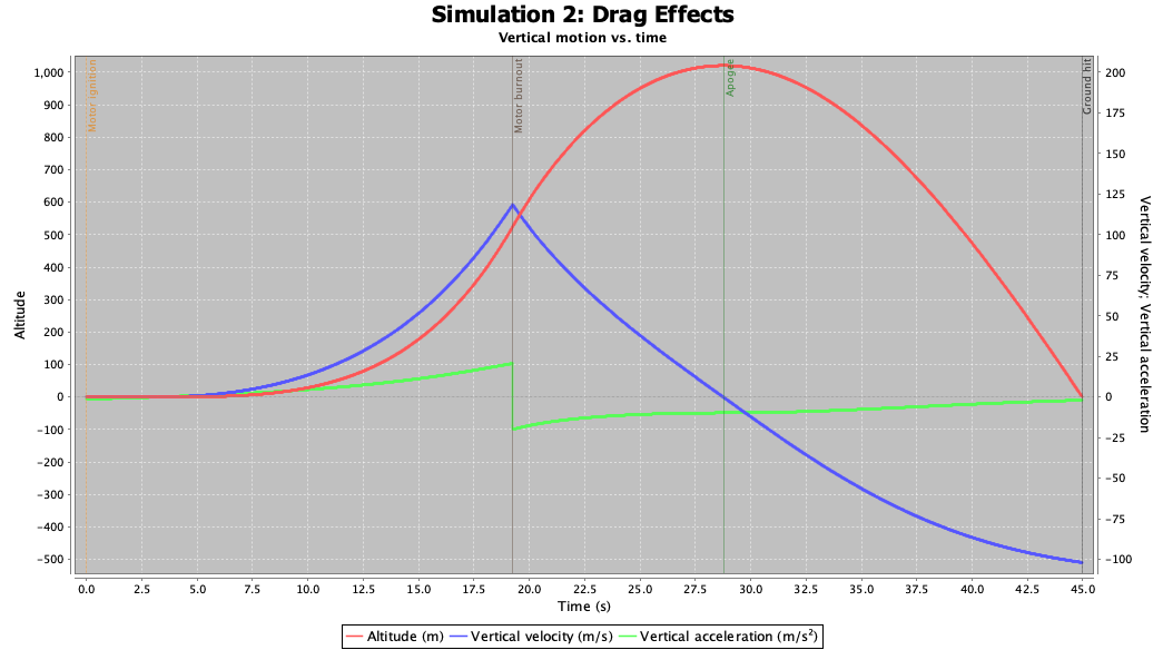
This result makes sense because, realistically rockets can have around 25% efficiency, and the simulation results show a similar result.
The effects of different geometry selction for rocket structure, structural material selection and propellent selection have also been observed in this section, which are included in the extended version of the report.
The overall project helped me to learn the aspects of theoretical rocket design and the realistic rocket performance with the environmental and structural limitation involved as opposed to the performance under ideal environment.
Reference:
[1] Paul Desjardin. “Class Lecture - MAE 423: Introduction to Propulsion, Spring 2020.” https://buffalo.app.box.com/s/8om64mmkqq3qflveaxufp90ofymasz17. Accessed 12 May 2020.
[2] James Barrowman. “Calculating the Center of Pressure of a Model Rocket.” http://www.rockets4schools.org/images/Calculating.pdf. Accessed 12 May 2020.